 by
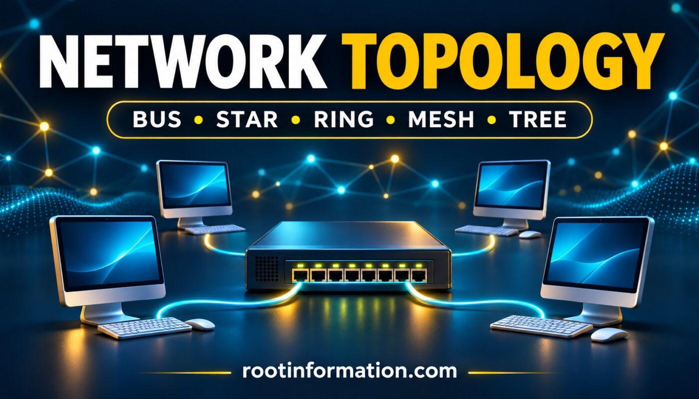
Network topology describes how computers and other devices connect in a network and how data moves between them. Common arrangements include bus, star, ring, mesh and tree. Understanding these layouts helps explain why some network failures affect one computer while others disconnect an entire office.
Imagine a classroom with ten computers. Connecting each computer to a central switch creates a different arrangement from connecting devices along one shared cable. The devices may perform similar tasks, but their connections introduce different strengths and weaknesses.
Before continuing, explore how computer communication began to understand the background of digital information exchange.
What Is Network Topology?
Network topology is the arrangement of nodes and links in a communication network.
A node is a connected device, such as a computer, switch or router. A link is a connection between nodes, which may use cables or wireless communication.
Topology helps answer practical questions:
- Which devices connect directly?
- Where does traffic travel?
- What happens when a connection fails?
- How can the network accommodate more devices?
The IEEE explanation of network topology describes both the physical layout and the logical relationships that determine traffic flow.
Physical and Logical Network Topology
Physical and logical topology describe different aspects of the same network.
| Aspect | Physical Topology | Logical Topology |
|---|---|---|
| Meaning | How devices and links are physically arranged | How data flows through the network |
| Main concern | Equipment placement and connections | Communication paths and forwarding behavior |
| Example question | Which switch connects to this computer? | Which path does traffic follow? |
The two layouts do not always match.
For example, older Ethernet networks using a hub could have a physical star arrangement while sharing a logical communication medium. A switched Ethernet network handles traffic differently, so the same assumption should not be applied to every star-shaped network.
Types of Network Topology
1. Bus Network Topology
In a bus topology, devices share one main communication cable, often called the backbone.
Think of several houses connected along one main road. The road represents the shared backbone, while each house represents a network device.
Main advantage: A simple shared-backbone arrangement can require relatively little cabling.
Main limitation: A fault in the backbone can interrupt communication across the shared segment. Traditional shared Ethernet also involves competition for access to the medium.
Bus topology is useful for understanding networking history. It should not be confused with the typical switched Ethernet layout used in a modern computer laboratory.
2. Star Network Topology
In a star topology, each device connects to a central device, typically a network switch in a wired LAN.
Example: Ten classroom computers each have a separate Ethernet connection to one switch.
If one computer’s cable disconnects, the other computers can usually continue communicating. However, if the only central switch fails, communication through that switch stops.
Main advantage: Individual connections are relatively easy to inspect and troubleshoot.
Main limitation: A basic star depends on its central device.
Cisco’s networking fundamentals material also illustrates an extended star, where a central switch connects to additional switches serving groups of computers.
3. Ring Network Topology
In a ring topology, devices form a closed loop. Each node has two neighboring connections in a simple ring.
Example: Four network devices connect in sequence, and the fourth connects back to the first.
Traffic behavior depends on the technology. Some ring systems send traffic in one direction, while others provide protection paths or support communication in both directions.
Main advantage: A protected ring can provide an alternative route when a link fails.
Main limitation: An unprotected ring may lose connectivity after a break.
Avoid assuming that every ring fails completely when one cable breaks. Cisco’s switch deployment guidance describes ring arrangements that use protocols to support redundancy.
4. Mesh Network Topology
A mesh topology provides multiple interconnections between nodes.
There are two common forms:
- Full mesh: Every node connects directly to every other node.
- Partial mesh: Selected nodes have additional connections, without every possible direct link.
Main advantage: Multiple paths can support continued communication after a link failure, provided the network can use the remaining paths.
Main limitation: Additional connections increase design, equipment and management requirements.
A mesh is not automatically faster or more secure. Its behavior depends on capacity, configuration and the technologies used.
5. Tree Network Topology
A tree topology organizes connections into branches and levels.
Example: A main switch connects to two departmental switches. Each departmental switch connects to its own group of computers.
Main advantage: The hierarchy makes it easier to organize departments or groups of devices.
Main limitation: A failed upstream device or connection can disconnect the branches that depend on it.
The AWS guide to network topology discusses tree arrangements alongside other common network structures.
Network Topology Comparison Table
| Topology | Basic Arrangement | Main Strength | Main Limitation |
|---|---|---|---|
| Bus | Shared backbone | Simple cable arrangement | Backbone failure affects the shared segment |
| Star | Devices connect to a center | Easier fault isolation | Central-device dependency |
| Ring | Closed loop | Protection paths are possible | Unprotected breaks can disrupt service |
| Mesh | Multiple interconnections | Alternative paths | Greater complexity |
| Tree | Hierarchical branches | Organized expansion | Upstream failures affect dependent branches |
These are general characteristics. Redundant equipment and suitable protocols can change how a particular network responds to failures.
Network Types vs Network Topology
Network coverage and network topology answer different questions.
PAN, LAN, MAN and WAN describe the scope or geographical reach of a network. Bus, star, ring, mesh and tree describe its connection arrangement.
For example, a school laboratory can be a LAN by coverage and use a star topology for its physical connections.
Remember this distinction:
- Network type: How broadly does the network extend?
- Network topology: How are its devices connected?
A Practical Network Topology Example
Imagine a small training center with twelve computers and one network printer connected to a central switch.
Consider three situations:
- One computer’s cable disconnects: Investigate that computer’s local connection.
- The switch loses power: Multiple connected devices may become unreachable.
- Internet access stops, but local printing works: The local network may still be functioning while the external connection has a problem.
This exercise shows why drawing the connection layout helps troubleshooting. It identifies which devices share a dependency.
If a printer is the affected device, our guide to fixing a printer offline in Windows 11 covers related troubleshooting steps.
Common Network Topology Mistakes
Confusing a Switch with a Hub
Both can appear at the center of a star, but they handle traffic differently. Do not assume their communication behavior is identical.
Assuming Redundancy Happens Automatically
Adding extra cables does not automatically create a reliable network. Redundant connections require suitable configuration and protocols.
Calling One Topology the Fastest
A layout alone does not determine speed. Equipment, link capacity, traffic and configuration all influence performance.
Network Topology FAQs
1. What Is Network Topology in Simple Words?
It is the arrangement of network devices and their connections, including how information flows between them.
2. Which Topology Uses a Central Switch?
A basic star topology connects devices to a central switch.
3. Which Topology Uses a Shared Backbone?
Bus topology connects devices through a shared main communication cable.
4. Does Every Ring Network Fail After One Cable Breaks?
No. Protected ring designs can provide an alternative path. The result depends on the network technology and configuration.
5. What Is the Difference Between Full and Partial Mesh?
A full mesh connects every node directly to every other node. A partial mesh includes only some of those direct connections.
6. What Is Hybrid Topology?
A hybrid topology combines different arrangements, such as star-connected groups linked through a mesh.
7. Is LAN a Network Topology?
No. LAN describes a local network’s scope. That LAN can use different connection arrangements.
Conclusion
Network topology explains the structure behind everyday network communication. Bus uses a shared backbone, star uses a central connection point, ring forms a loop, mesh provides multiple interconnections, and tree organizes devices into branches.
To understand each layout, ask what happens when one connection or device fails. This connects the definition to a practical problem and makes the differences easier to remember.